A Beginner's Guide to SpeedyBee F405 AIO
Wondering how to use your new SpeedyBee F405 AIO? Which models it's compatible with, and how to solder and assemble it? You’re in the right place! This guide will walk you through everything you need to know, from unboxing to using the advanced features of your flight controller.
01 Unboxing
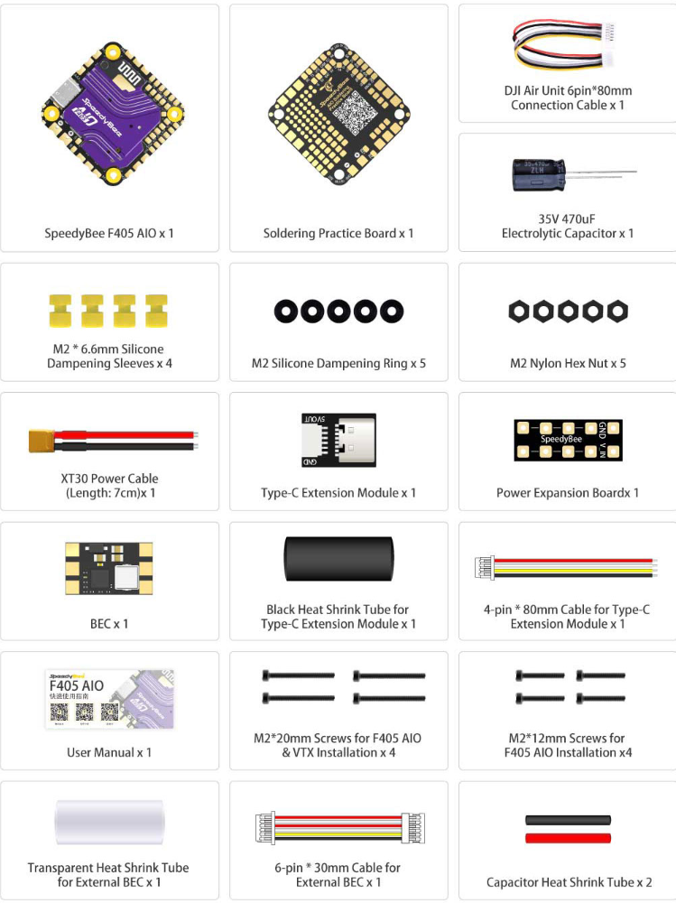
When you open the packaging, take out the SpeedyBee F405 AIO and its accessories. Here's what you can expect inside:

For a detailed unboxing experience, feel free to watch the video here.
1.2 Product Manual
https://support.speedybee.cn/?d=SF40A0&s=1000&a=p&l=en
1.3****Purpose of Each Component
1.3.1 BEC
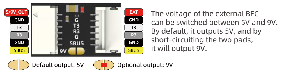
The BEC module paired with the F4 AIO supports 5V/9V voltage switching. By soldering to connect the two pads, you can select the output voltage, as shown in the image below.
(1)VTX Power Supply
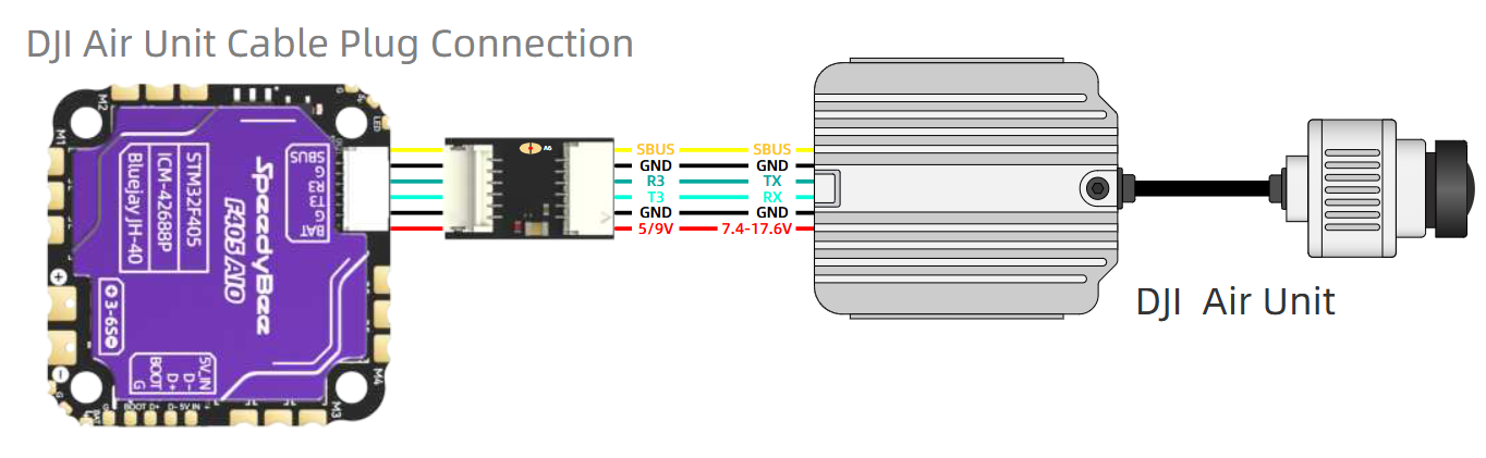
Power Requirements for Some VTX Devices: Certain VTX devices (such as the DJI first-generation air unit) do not support 6S voltage input and only operate within a 7.6-17.4V range. As a result, they cannot be connected directly to the Bat pad and need to be powered through a BEC.
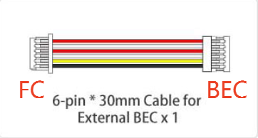
• Wiring Diagram: One end of the cable has an SH1.0 connector, while the other end has an NH1.0 connector. The SH1.0 end should be connected to the flight controller, and the NH1.0 end to the BEC.
Connection Diagram
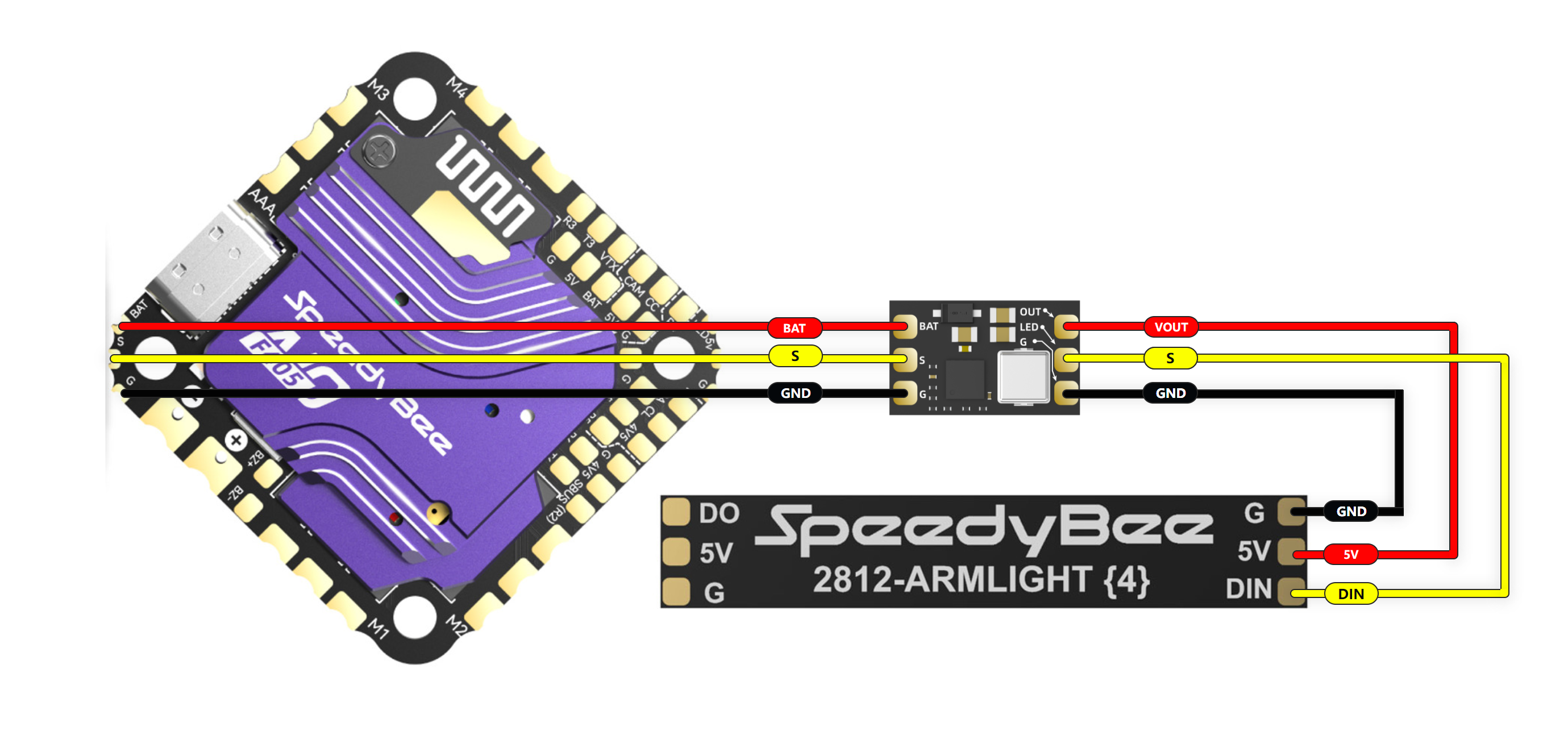
(2) LED Strip Power Supply
Flight Controller BEC Output Capacity: The 5V BEC of the flight controller supports a maximum output of 2A, which powers devices such as the main controller, receiver, camera, etc.
If the LED strip being used consumes more power (e.g., the LED strip on the BEE35, with a maximum current of 1.7A), an external BEC provided by us will be required for power supply. Please refer to the wiring diagram below.
(3) BEC Module Precautions
• Do not plug or unplug the BEC or devices connected to the BEC while the battery is connected (hot-swapping is not supported).
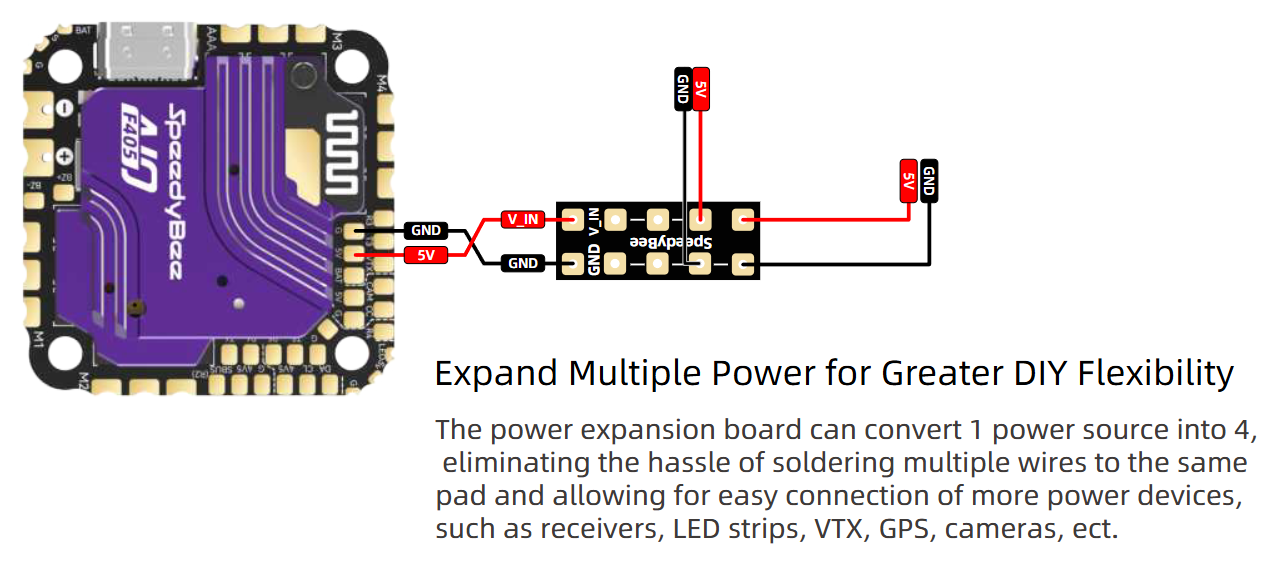
1.3.2 Power Expansion Board
The power expansion board allows the flight controller’s power output to be extended, making it easier to connect additional peripherals.
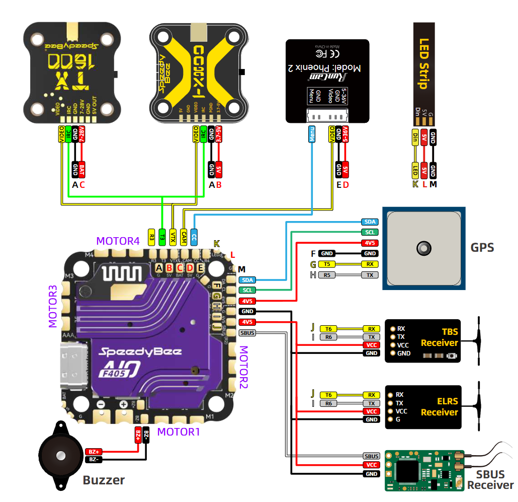
02 Peripheral Connections
The SpeedyBee F405 AIO features large solder pads, making it easy to solder and suitable for connecting various types of devices. You can solder components such as VTX, LED strips, motors, GPS, receivers, and buzzers to their respective spots as indicated by the labeled pads.
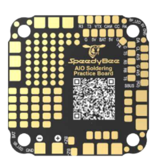
In addition, the package includes a soldering practice board to help you rehearse before actual operation, reducing soldering mistakes. You can scan the QR code on the practice board to access all the peripheral soldering tutorials. Alternatively, you can find the soldering tutorials for each peripheral in the "03 - Soldering Tutorials" section below.
03 Soldering Guide
To assist with the potentially tricky process of soldering various devices, we’ve provided detailed step-by-step guides for each.
3.1 Receiver
(1) ELRS Receiver
Please click here to view the ELRS receiver soldering tutorial.
(2) SUBS Receiver
Please click here to view the SUBS receiver soldering tutorial.
(3) TBS Receiver
Please click here to view the TBS receiver soldering tutorial.
3.2 Camera
Please click here to view the camera soldering tutorial.
3.3 Motor
Please click here to view the motor soldering tutorial.
3.4 GPS
Please click here to view the GPS soldering tutorial.
3.5 LED Strips
Please click here to view the LED strip soldering tutorial.
3.7 Power Cables & Capacitor
Please click here to view the power cables and capacitor soldering tutorial.
3.8 Buzzer
Please click here to view the buzzer soldering tutorial.
3.9 VTX
(1) TX800
Please click here to view the TX800 soldering tutorial.
(2) TX1600
Please click here to view the TX1600 soldering tutorial.
04 Wireless Firmware Flashing
Before taking off, you need to configure various parameters. The SpeedyBee F405 AIO supports Bluetooth functionality, allowing you to tune parameters, upgrade firmware, and modify motor direction through the SpeedyBee APP. You can also use the APP to click the DFU button, which will put the flight controller into recovery mode for wireless firmware flashing. Click here for a detailed guide on the wireless firmware flashing process.
05 Frequently Asked Questions (FAQs)
Q: Is the F405 AIO the same flight controller used in the SpeedyBee BEE25?
A: No, the F405 AIO has a continuous current rating of 40A, while the BEE25 AIO is rated at 35A. Additionally, the F405 AIO has a more stable and longer-range Bluetooth signal and features dual-sided CNC heat sinks for better heat dissipation.
Q: Does the ESC support bidirectional DShot?
A: Yes, the ESC comes with Bluejay 0.19.2 firmware, and supports enabling bidirectional Dshot.
Q: What version is the factory firmware of the flight controller?
A: Answer: The factory firmware of the flight controller is Betaflight 4.5.1.
Q: What is the factory firmware of the ESC?
A: Answer: The factory firmware of the ESC is Bluejay 0.19.2 J-H-40.
Q: Which SpeedyBee frames and motors are compatible with the F405 AIO? Do you have any recommended setups?
A: The F405 AIO is compatible with our BEE35, BEE25, and FLEX25 frames and supports SpeedyBee 2006-1950KV, SpeedyBee 1404-4600KV V2, and SpeedyBee 1404-4500KV motors.
Here are our recommended setups:
Setup 1: F405 AIO + BEE35 Pro Frame + SpeedyBee 2006-1950KV Motor + O3 VTX + Receiver
Setup 2: F405 AIO + BEE25 Frame + SpeedyBee 1404-4600KV V2 Motor + O3 VTX + Receiver
Setup 3: F405 AIO + FLEX25 Frame + SpeedyBee 1404-4500KV Motor + O3 VTX + Receiver
Q: What’s the difference between the SpeedyBee F405 AIO and the F745 AIO?
A: The F405 AIO offers a more affordable price, while also improving on stability, features, and accessories compared to the F745 AIO.
Q: Can I add a servo to the F405 AIO?
A: Yes, with INAV firmware, the CC pad can be used for servos. For Betaflight, manual mapping is required for servo pads.
Q: Is the F405 AIO compatible with Walksnail or HDZero?
A: Yes, it is compatible, but you need to match the correct wire order to use the direct plug on the SpeedyBee F405 AIO. If the system does not support wide voltage, you’ll need to use the included BEC to adjust the voltage to 9V before connecting.